Tag Technical Standards

Technical Standards Governing Penetrant and Magnetic Particle Testing

The importance of technical standards in Non-Destructive Testing

Non-destructive testing (END) is essential to ensure the integrity of equipment and components used in various industrial sectors.
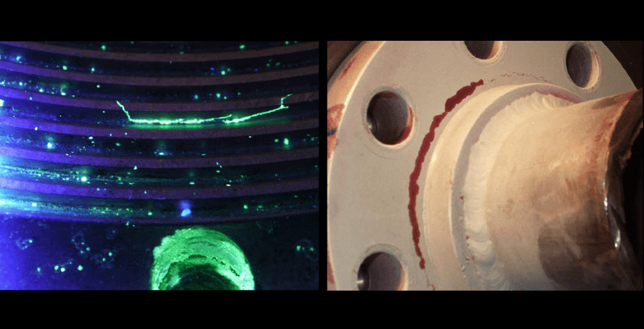
Among the most widely used methods are liquid penetrant testing (LP) and magnetic particle testing (PM).

Both allow the identification of discontinuities that could compromise the safety and performance of metal structures, welds, shafts, or castings, etc.

To ensure the quality and standardization of results, there is a set of national and international technical standards that establish criteria for execution, materials, and test conditions.

Next, see what these rules are and what each one determines in summary.


ASTM E1417 – Standard Practice for Liquid Penetrant Testing

It is the main international standard for the Penetrant Testing method .
It defines the essential parameters for the safe and accurate execution of the test, including:

  • Classification of penetrants (fluorescent and colored);
  • removal methods (water washable, post-emulsifiable, solvent removable);
  • lighting and sensitivity requirements;
  • stages of the process, such as cleaning, penetration, and development.
  • process controls.

ISO 3452 – Non-Destructive Testing – Penetrant Testing

The ISO 3452 series establishes international standards for materials and equipment.
Among its main topics are:

  • Part 1: General principles;
  • Part 2: Penetrant material requirements;
  • Part 3: Reference blocks;
  • Part 4: Equipment;
  • Part 5: Requirements for liquid penetrant testing at temperatures above 50 °C.

NM 334 – Non-destructive testing — Penetrant testing — Discontinuity detection

Mercosur standard that defines the main requirements for LP inspections in the national context, including:

  • technical terminology and symbology;
  • test stages (pre-cleaning, application, penetration, removal, development and evaluation);
  • minimum lighting levels;

ASTM E165 – Standard Practice for Liquid Penetrant Testing for General Industr y

Standard that defines the general procedures and criteria for liquid penetrant testing (LP) in industrial applications.
Establishes requirements for:

  • Classification of penetrants (fluorescent or colored);
  • removal methods (water, solvent or post-emulsifiable);
  • Control of lighting, temperature, and penetration time;
  • Sensitivity testing and product quality control.

PETROBRAS N-1596

Define:

  • test parameters and minimum/maximum process times;
  • procedural requirements;
  • lighting conditions;
  • Product classification and traceability;
  • Requirements for staff execution and qualification.

PETROBRAS N-2370

Provides:

  • General guidelines for safety, documentation, and traceability;
  • Penetrant testing.

ASME V – Art. 6

An integral part of the ASME Boiler and Pressure Vessel Code (BPVC) , it defines the requirements for penetrant testing applied to boilers, pressure vessels, and pressurized equipment.
It contains:

  • Specifications for materials and equipment;
  • sensitivity check of the test system;
  • process control and inspection intervals;
  • Acceptance according to manufacturing codes.

ASTM E709 – Standard Guide for Magnetic Particle Testing

The principal international standard governing magnetic particle testing .
It establishes best practices and application guidelines for:

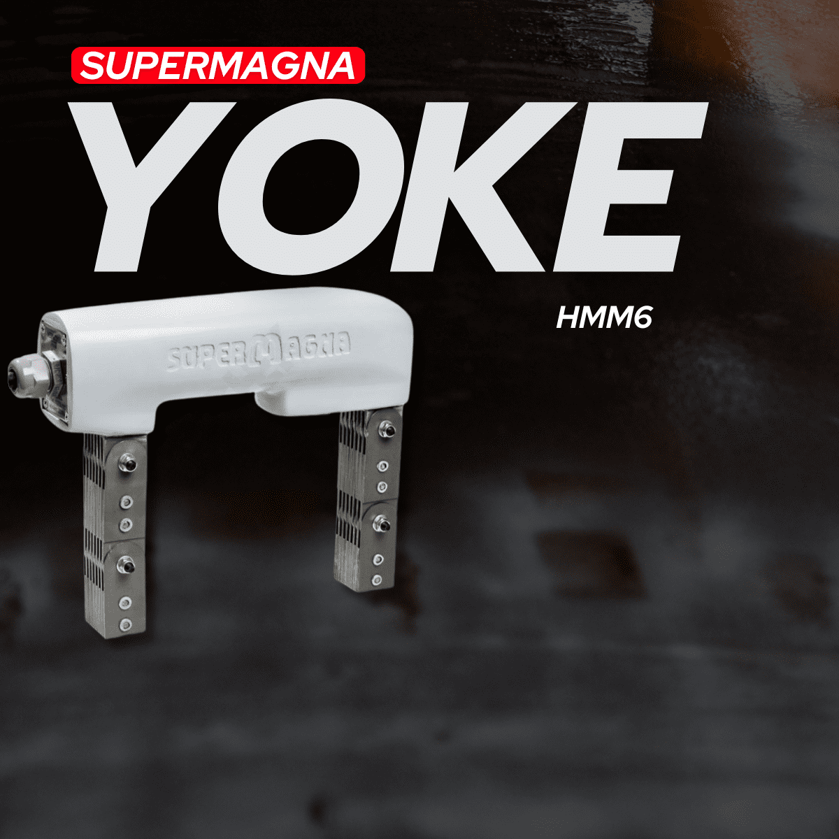
  • Magnetization techniques (yoke, electrodes, coil, center conductor and direct contact);
  • use of colored and fluorescent particles;
  • Electrical current control and field direction;
  • Verification of particle concentration and illumination (visible and UV).

ASTM E3024 – Standard Practice for Magnetic Particle Testing for General Industry

It complements ASTM E709 and provides specific instructions for inspections in general industry .


NM 342 – Non-destructive testing — Magnetic particles — Discontinuity detection

It establishes technical parameters for conducting the test in accordance with international standards:

  • Dry and wet application;
  • characteristics of magnetic particles and liquid vehicles;
  • Recommended concentration ranges for wet application (0.1 to 0.4 mL for fluorescent and 1.2 to 2.4 mL for colored);
  • Light intensity control for visible and UV-A light.

ASTM E1444 – Standard Practice for Liquid Penetrant Testing for Aerospace

Specifically for the aeronautical and aerospace sector , it defines detailed practices for magnetic particle (PM) testing .
It establishes:

  • requirements for magnetic materials and vehicles;
  • concentration limits and bath control;
  • UV-A and white light checks;
  • Strict calibration and acceptance criteria.

PETROBRAS N-1598

It defines the criteria for performing the PM method on ferromagnetic materials.
It covers:

  • magnetization techniques;
  • UV lighting requirements and field strength;
  • calibration procedures.

ASME V – Art. 7

Part of the ASME Boiler and Pressure Vessel Code , it defines the requirements for magnetic particle testing of pressurized equipment and welded components.
It covers:

  • Types of electric current and magnetization techniques;
  • magnetic field intensity control;
  • detection methods;
  • Acceptance and qualification criteria for the testing system.

ISO 9934 – Non-Destructive Testing – Magnetic Particle Testing

The ISO 9934 series establishes international standards for materials and equipment.
Among its main topics are:

  • Part 1: General principles;
  • Part 2: Detection method;
  • Part 3: Equipment;

Importance of technical standards for the reliability of END (Non-Destructive Testing).

The standards governing liquid penetrant and magnetic particle methods are the technical basis that ensures reliability and regulation  of Non-Destructive Testing.
They guide everything from product development to practical application in the industrial environment, ensuring quality, safety, and standardization in every inspection.

Knowing these standards is essential for anyone working in quality control, maintenance, and inspection — whether in heavy industry, petrochemicals, aeronautics, or metallurgy.


Important notice:

This content is for educational purposes only. The application of the test methods and parameters must follow a qualified procedure approved by a Level 3 Inspector .


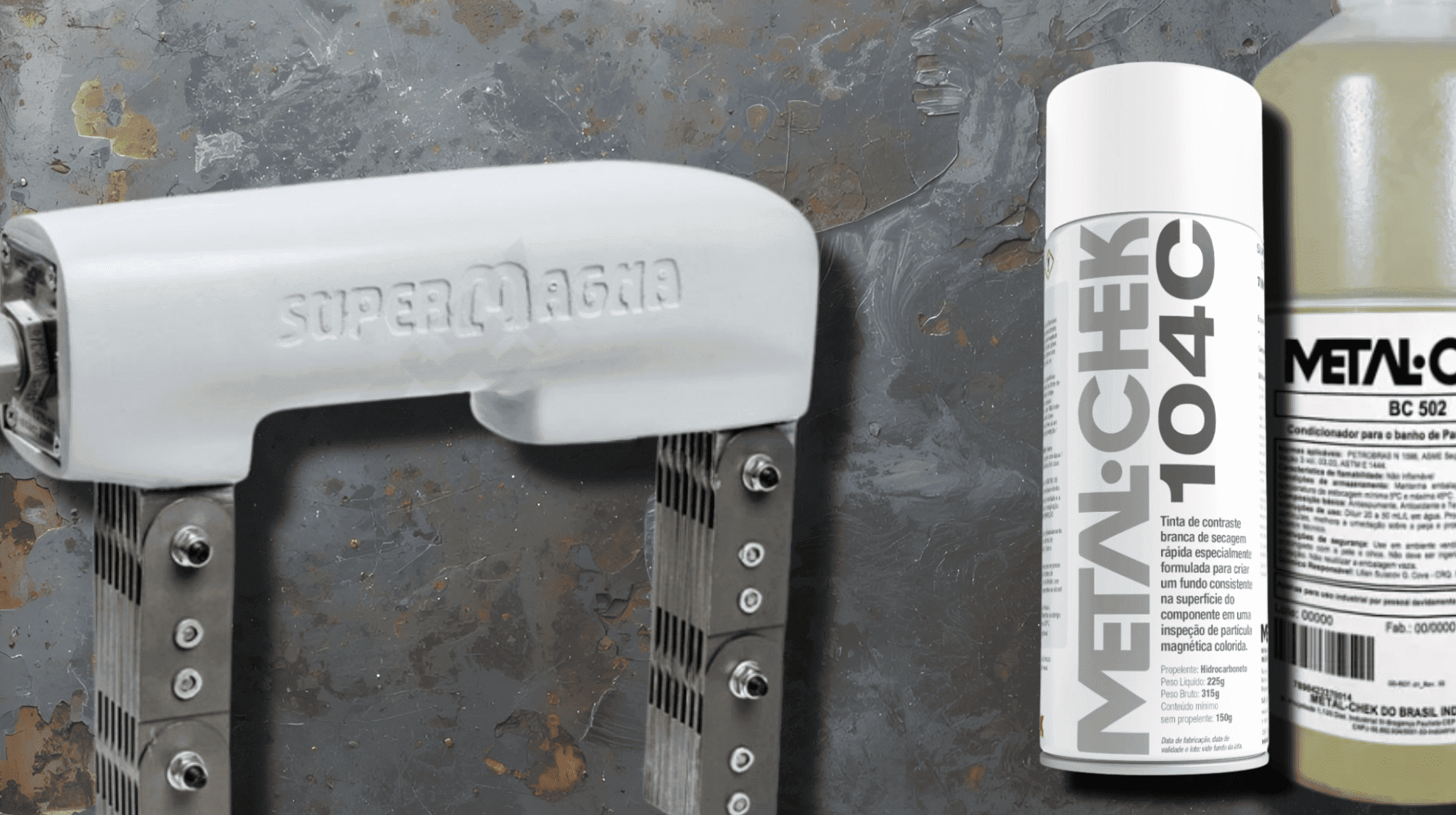
Solution in Non-Destructive Testing

Metal-Chek provides complete END solutions: penetrant liquids , magnetic particles , yoke and accessories , developed according to the main ASTM, ISO , ASME, NM, PETROBRAS standards, guaranteeing quality, safety and technical compliance in every inspection.

Discover the complete Metal-Chek product line.

Contact our team.

Follow @metalchek

Complete Magnetic Particle Inspection

THE POWER OF COMBINATION

Discover how the combination of Supermagna Yoke HMM6 , magnetic powder particles , BC 502 SN Conditioner and 104C Contrast ensures fast, compliant and safe magnetic particle inspections .

In industrial maintenance, the reliability of inspections is crucial to avoid rework, equipment failures, and costs associated with unscheduled downtime.

Among Non-Destructive Testing (END) methods, magnetic particle inspection (MPI) is one of the most widespread techniques for detecting surface and subsurface discontinuities in ferromagnetic materials .

For reliable results, good magnetization equipment alone is not enough. High-quality magnetic particles, a suitable conditioner, and an effective contrast agent are also necessary .

This is where Metal-Chek stands out, offering a robust combination for the industry: the Supermagna Yoke HMM6 , magnetic powder particles associated with the BC 502SN Conditioner and the 104C Contrast .


Supermagna Yoke HMM6: Robustness and Compliance

The Supermagna Yoke HMM6 is an electromagnetic yoke designed to generate the necessary magnetic field during inspection.

Main features:

  • Portable and robust – ideal for field and factory inspections.
  • Safe – it does not conduct current through the part, but induces a longitudinal magnetic field.
  • Versatile – suitable for inspecting welds, castings, forgings, metal structures, etc.

Regulatory – complies with the main national and international standards.


Magnetic Particles + BC 502 SN Conditioner

The use of magnetic powder particles , combined with BC 502 SN Conditioner , is the most widely adopted method for forming stable and efficient suspensions.

Function of magnetic particles:

  • They make surface and subsurface discontinuities visible by accumulating in regions where the applied magnetic field escapes.
  • The concentration can be adjusted according to the procedure.
  • Available in different options for visible or fluorescent inspections.

Function of BC 502 SN Conditioner:

  • It guarantees corrosion protection .
  • Allows for uniform dispersion of particles .
  • It promotes proper moisturization and mobility  on the surface.
  • Compliant with technical standards requirements.

104C Contrast: Enhanced Visibility and Precision

Contrast 104C is applied before magnetization and magnetic particle bathing, creating a uniform white background .

Main functions:

  • It increases the contrast between the particles and the surface.
  • Increased sensitivity of the assay.
  • Compliance with technical standards.

How the Combination Works

  1. Applying Contrast 104C – creates a contrasting and uniform white background.
  2. Magnetization with the Supermagna Yoke HMM6 – generates the necessary magnetic field.
  3. Application of the prepared suspension (particles + BC 502 SN) – the particles agglomerate in the leakage field regions, forming indications.
  4. Interpretation – with a white background and highlighted particles, the inspector can quickly and reliably identify discontinuities.

Advantages of the Combination

  • High sensitivity in detecting discontinuities.
  • Operational speed , with results visible immediately.
  • Regulatory reliability , in accordance with ASTM, ISO, AMS, ASME and PETROBRAS standards.
  • Flexibility , allowing adjustments to particle concentration.
  • Safety is ensured through the use of a robust and secure yoke in various environments.

Technical Standards Supporting the Set

The combination meets the requirements of international and national standards, such as:

  • ASTM E709
  • ASTM E3024
  • ISO 9934 (1 and 2)
  • NM 342
  • ASME BPVC Section V, Article 7
  • PETROBRAS N-1598

Magnetic particle inspection is an essential technique for industrial maintenance and quality assurance . However, its efficiency depends on choosing the right equipment and supplies .

The combination of the Supermagna Yoke HMM6 , magnetic particles with BC 502 SN Conditioner , and 104C Contrast ensures a fast, reliable, and safe inspection process.

With this complete solution, Metal-Chek reinforces its commitment to providing cutting-edge technology for Non-Destructive Testing , meeting the needs of the industry with excellence.

Speak with our  technical team  and discover how we can help transform your inspection routines into competitive advantages. 

Follow us on Instagram: @metalchek

How to Perform an Efficient Magnetic Particle Inspection: A Guide for Professionals

Discover how to plan and execute magnetic particle inspections, ensuring speed, reliability, and compliance with technical standards.


Industrial inspections can present challenges such as lack of infrastructure, space limitations, adverse conditions, and the need for fast and reliable results .

In this context, Non-Destructive Testing (END) using magnetic particles (MP) stands out as a practical solution for detecting surface discontinuities in ferromagnetic materials .

This practical guide is aimed at maintenance professionals, inspectors, and engineers , showing how to perform magnetic particle inspections efficiently, safely, and in compliance with regulations , even outside of controlled laboratory environments.


Surface Preparation

One of the biggest challenges in inspections is dealing with surfaces contaminated by grease, oil, welding spatter, or oxidation. Proper area preparation is essential to avoid false readings.

Recommended techniques:

• Steel brush (manual or rotary): quick removal of oxidation from welds and metal structures.
• Grinding: suitable for removing coatings and persistent oxidation.
• Solvents and clean cloths: remove grease and oils.

The better the preparation, the greater the reliability of the inspection.


Choice of Technique

The type of application of magnetic particles should consider environmental conditions, available time, and required sensitivity .

  • Dry process:

Advantages → ideal for surfaces with high temperatures

Limitations → lower sensitivity to small discontinuities

  • Wet method (water or oil):

Advantages → high sensitivity, suitable for detecting small discontinuities.

  • Colored wet process

Advantages → visible under white light, no need for special lighting fixtures.

Limitations → operating temperature

  • Fluorescent wet particles:

Advantages → maximum sensitivity under UV-A light.

Limitations → operating temperature, visible only under UV-A light.


Safety in Confined Spaces

Inspections of tanks, vessels, and confined structures require additional safety measures:

  • Use portable and robust equipment , such as the Supermagna Yoke HMM6 , which works in different positions and does not conduct current through the workpiece.
  • Respect occupational safety standards (e.g., NR-33 – Safety in Confined Spaces).

Choosing robust equipment is crucial for reducing risks and increasing reliability in challenging environments.


Technical Standards Governing Testing

Magnetic particle inspection can follow recognized standards to ensure reliable results:

  • ASTM E709
  • ISO 9934 (1 to 2)
  • PETROBRAS N-1598
  • ASME Section V, Article 7

Recommended Equipment for Inspections

For magnetic particle inspections, the ideal solution is to use equipment that combines durability, safety, and regulatory compliance.

The Supermagna Yoke HMM6 , for example, is designed to meet these needs:

  • Portable and robust.
  • Safe in potentially explosive atmospheres.
  • Meets ASTM, ISO, ASME and PETROBRAS standards.
  • Suitable for inspections of welds, metal structures, castings, forgings, etc.

Magnetic particle inspection is a strategic tool for industrial maintenance. When performed correctly — with proper surface preparation, appropriate technique selection, and the use of reliable equipment — it ensures operational safety, regulatory compliance, and cost reduction .

If your company operates in sectors such as oil & gas, energy, automotive or metallurgical , the Metal-Chek Supermagna Yoke HMM6 is the ideal solution to guarantee reliable results within standards .

Speak with our technical team.

Follow us on: @metalchek

How to Choose the Ideal Penetrant Type for Each Application – Non-Destructive Testing

In penetrant testing, choosing the correct product is crucial for the  sensitivityreliability, and compatibility of the test. Specifying an inappropriate penetrant can lead to incomplete detection of discontinuities, material damage, or even unnecessary rejections.

This guide will help you understand which factors to consider  and how to select the most suitable penetrant for your application, with real-world examples from the Metal-Chek line.


1. Begin by understanding the classification of penetrants.

Penetrant liquids are classified primarily by  typeremoval method, and sensitivity level.

a) Type

  • Type I – Fluorescent.
    High sensitivity, inspection under UV light. Ideal for detecting very fine discontinuities.
    Ex.:  Metal-Chek FP 91 , Type I, Method A, Level 2.
  • Type II – Visible.
    Indications visible to the naked eye under white light. Simpler and faster, ideal for field inspections.
    Ex.:  Metal-Chek VP 30 , Type II, Method A;  Metal-Chek VP 31 , Type II, Method C.

b) Removal method

  • A – Washable with water  (easy removal with water)
  • B – Lipophilic post-emulsifiable  (emulsifier applied after the penetrant)
  • C – Solvent removable  (removal with cloth and solvent, such as  Metal-Chek E 59  or  Metal-Chek R 501 )
  • D – Hydrophilic post-emulsifiable  (water-based emulsifier)

c) Sensitivity level (Type I)

It ranges from  Level 1  (low sensitivity) to  Level 4  (ultra-high). The more critical the component, the higher the recommended level.


2. Consider the material to be inspected.

  • Stainless steels, titanium, and special alloys : require penetrants with low halogen and sulfur content, and compatible developers.
    Ex.:  Metal-Chek FP 91  with contaminant certification according to ASTM E165.
  • Carbon steel and ferrous materials : greater flexibility of choice, depending on the acceptance criteria.
  • Porous materials : require care to avoid excessive penetration and false readings.

3. Inspection environment and conditions

  • Environments with low, controlled lighting : fluorescent (Type I) is preferable.
  • Field inspection or areas with restricted UV lighting : opt for visible (Type II).
  • Locations without running water : consider method C (removable solvent) for cleaning up excess water.

4. Compliance with standards and criteria

Always align the penetrant and developer with the required standard:

  • ASTM E165, ISO 3452, ASME Section V, Petrobras N-1596.
    And include in the RFQ the requirement for a batch certificate and SDS (Safety Data Sheet).

5. Combining penetrant, developer, and remover

For an effective test, choose a compatible set:

  • Metal-Chek FP 91  (fluorescent) +  Metal-Chek D70  (non-aqueous developer) +  Metal-Chek E 59  (solvent remover).
  • Metal-Chek VP 30  (visible) +  Metal-Chek D72  (dry developer) +  Metal-Chek R 501  (solvent remover).

Conclusion

Choosing the right penetrant is not just a matter of preference — it’s  a guarantee of reliable results and compliance with technical standards .
Metal-Chek offers solutions for different sensitivity levels, methods, and types, always accompanied by technical certification and specialized support.

Contact the Metal-Chek technical team.

Follow us on Instagram:  @metalchek

Read also:

The Main Methods of Industrial Inspection and How to Choose the Ideal One

How to Choose the Ideal Penetrant Testing Process for Your Application?

Do you know what makes a penetrating liquid effective?

Visual Inspection (Visual Testing – VT): The First Steps to Identify Equipment Faults

Every effective inspection begins with observation — not just what the eyes see, but what a technical and experienced eye is able to interpret. Visual Inspection (VI) is the initial step in identifying discontinuities , defects, wear, and anomalies that can compromise the integrity and performance of equipment.

More than just a superficial check, VT acts as an initial filter in quality control, directly contributing to cost reduction , risk prevention , and increased operational efficiency .

Furthermore, visual inspection serves as the gateway to more advanced non-destructive testing techniques, such as penetrant testing, magnetic particle testing, and ultrasound. In other words, when a visual indicator is detected, it’s the right time to deepen the analysis with complementary and more sensitive methods.

Although it seems simple, visual inspection requires much more than just “looking”:

  • Technical training
  • Knowledge of acceptance criteria
  • Adequate lighting
  • Support tools and instrumentation
  • Evidence documentation

Visual Inspection in the Industry 4.0 Era

Those who think that Visual Inspection (VI) has lost importance with the advancement of automation are mistaken. On the contrary — it has evolved and integrated with new technological resources, expanding its reach, precision, and speed.

Today, VT is an active part of Industry 4.0 and can be combined with state-of-the-art digital solutions:

  • Artificial intelligence for image recognition.
  • Drones for inspections at heights or in hazardous areas.
  • 4K cameras with thermal sensors
  • Predictive analytics connected to digital dashboards

Most common applications of visual inspection.

Visual Inspection (VI) is widely used in various industrial sectors as a quick and effective assessment tool. Its main objective is to identify visible irregularities that may compromise the structural integrity, functionality, or safety of components and equipment.

The following table summarizes the main applications and what is sought to be identified in each case:

ApplicationWhat are we trying to identify?
WeldingCracks, porosity, lack of fusion or penetration
Pressurized equipmentCorrosion, deformation, leaks
Metal structuresDeformations, warping, cracks
Ducts and pipingLeaks, oxidation, deterioration
Machines and moving partsWear and tear, misalignment, fractures

Equipment and Resources Used in Visual Inspection

Although many visual inspections are done with the naked eye, the use of auxiliary equipment significantly enhances the accuracy and reliability of the test. Some resources used include:

 Adequate natural or artificial light: Ensures adequate visibility. Poor lighting can compromise the detection of discontinuities.

Magnifying glasses and magnifying lenses: They amplify small details, allowing the identification of surface cracks, porosity, inclusions, or lack of fusion in welds.

Borescopes and industrial endoscopes: Optical instruments used for inspecting hard-to-reach areas, such as pipes, internal welds of pressure vessels, and aeronautical components.

Rulers, gauges and jigs: Tools for measuring dimensions, weld angles, weld bead profiles and alignments.

High-resolution cameras: They facilitate photographic documentation and historical comparison during periodic inspections.

Digital inspection and recording software: With the advancement of Industry 4.0, integrating visual inspections with digital systems allows for recording occurrences, generating reports, and maintaining traceability in accordance with regulatory requirements.

Tip:
In low-light environments, the use of adequate artificial light is not optional — it’s mandatory.

Best practices in performing visual inspections.

To ensure the effectiveness of visual inspection and the reliability of results, it is essential to adopt well-defined operational practices. Standardizing execution through written procedures and operational checklists helps minimize human error and ensure consistency in assessments. A simplified model is presented below that can be adapted to the needs of each sector:

BEFORE INSPECTION:

  • Check that the surface is clean (free of contaminants such as paint, oil, grease, rust, dust, or debris).
  • Check the ambient lighting (it should be sufficiently intense and evenly distributed, allowing for an accurate assessment of the surface. It is important to avoid reflections, shadows, or glare, especially on polished materials or those with irregular geometry. In locations with little natural light, the use of adjustable and directional artificial light sources is recommended to ensure good visibility).
  • Assess the inspector’s physical and visual condition (e.g., fatigue, use of glasses).
  • Assess the need for additional equipment and resources.

DURING THE INSPECTION:

  • Observe surface continuity: deformations, cracks, oxidation.
  • Check weld beads: profile, spatter, lack of fusion.
  • Use magnifying glasses on areas with suspicion or small details.
  • Photographing and documenting irregularities
  • Assess the need for additional tests (liquid penetrant, magnetic particles, etc.).

AFTER INSPECTION:

  • Record keeping and traceability (maintaining a history of inspections, photos, reports, inspection maps, and checklists with acceptance criteria. These records ensure traceability, effective audits, and support decision-making).
  • Storing records digitally ensures traceability and facilitates audits.

Integration of Visual Inspection with Other END Methods

Visual Inspection (VI) is the starting point for most Non-Destructive Testing (END). While it can identify various surface flaws, it does not always provide sufficient information for a complete assessment of the component’s integrity. Therefore, it is essential to integrate it with complementary methods, especially when there are visual suspicions that require technical confirmation.

The table below shows how VT connects to the main END methods and the benefits of this combination:

Complementary MethodApplication after VTCombined benefits
Penetrant Testing (PT)Detection of cracks and open discontinuities on the surface.Confirms and verifies suspicious visual indications.
Magnetic Particles (MP)Inspection of ferromagnetic parts. Detects surface and subsurface flaws.Increased sensitivity in critical areas, such as welds.
Ultrasound (UT)Assess the internal integrity of the part.It identifies internal flaws that are not visible externally.
Radiography (RT)Reveals volumetric discontinuities in welds and castings.High reliability and permanent visual documentation.

Normative References

Visual inspection is governed by several technical standards that ensure standardized procedures, reliable results, and compliance with legal and industrial requirements. Below, we highlight some applicable technical standards:

  • ISO 17637 – Visual Inspection of Welds in Metallic Materials: establishes requirements for performing visual inspection of welds, including acceptance criteria and recommended techniques.
  • NBR 14842 – Visual Inspection of Welds: national procedures and requirements that guide the practice of visual inspection of welds.
  • ASME Section V, Article 9 – Requirements for Visual Inspection: a standard widely used in the pressure equipment and boiler making industry.
  • Petrobras Technical Standards (Examples: N-1596, N-1598, N-2370) – Specific guidelines for visual inspections in the oil and gas sector.

The First Line of Defense for Quality

Visual inspection is much more than just a keen eye—it’s an essential technical barrier against failures that compromise safety, productivity, and regulatory compliance.

Implementing a well-structured visual inspection program is the first step towards operational excellence. Furthermore, when combined with Metal-Chek methods such as Liquid Penetrant, Magnetic Particle, and Leak Detection , visual inspection transforms into an ecosystem of industrial reliability .

Next Steps for Your Company

To strengthen your visual inspection program and increase the reliability of your processes, consider:

✅ Assess the maturity of your visual inspection program.

✅ Empower your team with training based on recognized standards.

✅ Standardize checklists and procedures with specialized technical support.

✅ Invest in quality accessories and equipment to complement the visual stage.

If your company wants to increase process reliability and ensure technical compliance, Metal-Chek is your ideal partner.

Speak with our technical team and discover how we can help transform your inspection routines into competitive advantages. 

Follow us on Instagram:  @metalchek

Contact us at: (11) 3515-5287

The Importance of Calibration in END Equipment for Reliable Results

If you want to guarantee accuracy, compliance, and operational safety in your Non-Destructive Testing (END), equipment calibration is not an optional step—it’s indispensable.
Companies that neglect this practice face serious risks:
❌ Inaccurate reports
❌ Undetected failures
❌ Non-conformities in audits
❌ Operational and reputational damage

➡️ When equipment is out of calibration, reliability disappears — along with operational safety.

What is Calibration and why is it Vital in END?

Calibration is a process of comparing two instruments (the measurand and the measured). This comparison involves calculating error and uncertainty, and these results are presented in a document called a calibration certificate.

  • ✅ Relationship between measurement values ​​and uncertainties; 
  • ✅ Technical standards are being met;

Standards such as ASME Section V, ASTM E1417, ASTM E1444, ASTM E3024, and ASTM E709 require that your equipment be calibrated for the results to have technical and legal validity.

Why is calibration a key differentiator?

1. Ensures Technical Precision

  • False positives → good parts are discarded unnecessarily.
  • False negatives → errors go unnoticed.

Both put security at risk, increase costs, and compromise the company’s reputation.

2. Avoid Penalties in Audits

Industries such as oil and gas, aeronautics, rail, and automotive are inflexible regarding non-compliant equipment.
Golden tip: Always demand certificates traceable to the RBC (Brazilian Calibration Network) or recognized international standards.

3. Reduces costs associated with rework.

Investing in calibration is cheaper than correcting errors caused by miscalibrated equipment.

Which equipment needs to be calibrated?

Penetrant Testing (PT)

  • Radiometers/Photometers
  • Thermometers
  • Water pressure gauges
  • Compressed air pressure gauges

Magnetic Particle (MP)

  • Gaussmeters (Residual)
  • Magnetic Field Meters
  • Ammeters
  • Timers
  • Magnetizing equipment (Stationary Machines)
  • Settling tubes

When should the equipment be calibrated?

The ideal calibration frequency is determined according to applicable standards.

How to Guarantee Traceability?

Compliance isn’t something you improvise. Follow these practices:

  • ✔ Hire laboratories accredited by Inmetro (ABNT NBR ISO/IEC 17025);
  • ✔ Archive and update calibration certificates;
  • ✔ Use digital checklists with automatic due date alerts;

[PRACTICAL CHECKLIST] How to Organize Your Calibration Routine

StepAction
PlanningMap all equipment that requires calibration.
HiringChoosing an accredited laboratory
Follow-upCreate due date alerts
DocumentationArchive calibration certificates and evidence.
Internal VerificationUse reference standards for control.

Calibration means Safety, Reliability, and Quality.

In the world of Non-Destructive Testing, calibration is an act of technical responsibility and a commitment to safety .

Metal-Chek offers the best consumables and accessories to ensure your penetrant testing, magnetic particle testing, and leak detection are accurate, traceable, and reliable.

You may have the best partner laboratory — but if your products are not of high quality, the results will be compromised.

Ready to increase the reliability of your tests?

→ Contact our technical team right now.
We’ll help you select the best Metal-Chek products to make your tests safer and more effective.

Follow us on Instagram:  @metalchek

Contact us at: (11) 3515-5287

Planning an Effective Non-Destructive Testing Program: Essential Checklist

The role of inspections in modern industrial maintenance.

Industrial maintenance has evolved by leaps and bounds in recent decades. With the advancements of Industry 4.0 , new technologies, sensors, and continuous monitoring systems have been integrated into the daily operations of factories and industrial plants. However, no matter how innovative these emerging technologies are, one foundation remains unshaken: inspection through Non-Destructive Testing (END) .

Inspecting without causing damage to parts and structures is a technical, economic, and strategic advantage. In sectors where safety and reliability are critica l— such as oil and gas, aeronautics, automotive, civil construction, metallurgy, and industry and commerce in general — END (Non-Destructive Testing) is indispensable for predicting failures, ensuring the integrity of components, and increasing the lifespan of assets.

In this article, we will present a practical guide to structuring an effective non-destructive testing program. We will cover what should be taken into account, which professionals should be involved, when to apply the techniques, and how to document and interpret the results. By the end, you will have an essential checklist that can be adapted to different industry realities .

Why plan a Non-Destructive Testing program?

Imagine a ship undertaking long sea voyages. Instead of waiting for something to break at sea, a routine of inspections allows for the identification of cracks, corrosion, and structural flaws before they become catastrophic. This applies to an urban bridge, mining equipment, or a pressure vessel in a chemical plant.

A well-structured END (Non-Destructive Testing) program is the cornerstone of efficient industrial maintenance , integrated with the philosophy of predictive maintenance , operational reliability, and occupational safety. Furthermore, it reduces costs associated with unplanned downtime and serious failures.

Essential Checklist: How to Structure an END Program

1. Identify the critical assets.

The first step to an efficient plan is knowing what will be inspected . Make a list of the plant’s most critical assets: equipment operating under high pressure, structures subject to repetitive stress, components exposed to corrosion, or welds in strategic locations.

Practical tip: use tools such as FMEA (Failure Mode and Effects Analysis) or RCM (Reliability-Centered Maintenance) to identify assets that deserve more attention.

2. Define clear objectives.

Each inspection should have a purpose: to detect cracks? To assess the quality of a weld ? To check for leaks using penetrant testing ? Define the objectives to determine the best technique and frequency of evaluation.

3. Choose the appropriate Non-Destructive Testing methods.

ENDs encompass a range of methods. Among the most common are:

  • ◽ Penetrant Testing (PT): ideal for detecting surface cracks in non-porous metals. Widely used in weld inspection.
  • ◽ Magnetic Particles (MP): efficient for detecting surface and subsurface discontinuities in ferromagnetic materials.
  • ◽ Ultrasound (UT): allows for the verification of internal defects, material thickness, and density variations.
  • ◽ Industrial Radiography (X-ray): ideal for detecting volumetric flaws in welded joints or cast parts.
  • ◽ Visual Inspection (VI): the first line of defense, it must be carried out systematically, with appropriate equipment and lighting.

The choice depends on the type of material, the defect to be detected, the applicable technical standards, and operational feasibility.

4. Determine the frequency of inspections.

Each piece of equipment has an estimated lifespan, but actual operating conditions can accelerate wear and tear and failures. Therefore, the frequency of inspections should consider:

  • ◽History of failures
  • ◽Operating environment (abrasive, corrosive, humid)
  • ◽Mechanical loads and stresses
  • ◽Specific regulatory standards (e.g., NR-13 for pressure vessels)

Practical example: in sectors involving constant inspection and welding , such as boiler making and oil pipelines, the frequency should be more rigorous.

5. Develop standardized operating procedures (SOPs).

Having standardized operating procedures (SOPs) is essential to ensure repeatability, traceability, and quality. These procedures should include:

  • ◽Techniques to be applied
  • ◽Surface preparation steps
  • ◽Equipment and consumables used
  • ◽Acceptance and rejection criteria
  • ◽Photographic records and reports

At Metal-Chek, for example, penetrant , developer, and remover fluids comply with AMS 2644 and Petrobras N-2370 standards, ensuring standardization in critical inspections.

6. Train the technical team.

The professionals responsible for applying END (Non-Destructive Testing) must be qualified, according to the requirements of the ABNT NBR ISO 9712 standard or equivalent international standards. They are classified into three levels:

  • Level 1: Performs inspections following detailed instructions.
  • Level 2: Interprets results, prepares reports, and instructs Level 1.
  • Level 3: Designs and validates procedures, leads audits, and ensures regulatory compliance.

An industry that invests in training and certifying its team reaps the rewards in reliability, safety, and performance.

7. Document and manage the results.

Photographic records, reports, and historical data should be stored in an organized manner. This facilitates trend analysis, audits, and the planning of corrective actions. With the digitization of processes and the arrival of Industry 4.0 , integrated management platforms with IoT, sensors, and cloud databases make this process more agile and secure.

Integration with Industry 4.0: END as a link between technology and reliability.

A well-planned inspection program goes beyond conventional maintenance. It integrates with the emerging technologies of Industry 4.0 .

  • ◽ Onboard sensors detect vibration, temperature, or microcracks in real time.
  • ◽ Predictive systems warn when a component is close to failure.
  • ◽ Robotic inspections in hard-to-reach locations increase safety.
  • ◽ Predictive analytics software cross-references historical data with recent inspections to predict future failures.

In other words, non-destructive testing ceases to be a one-off action and becomes a strategic part of the company’s operational intelligence.

Inspections and Welding: A Critical Relationship

A large proportion of structural failures originate from poorly executed or degraded welds over time. The correct application of END (Non-Destructive Testing) in this context is vital for:

  • ◽ Ensure weld quality during manufacturing.
  • ◽ Detect thermal or fatigue cracks
  • ◽ Control stress corrosion cracking (especially in harsh industrial environments)

Techniques such as liquid penetrant and magnetic particles are particularly effective in this scenario, with the advantage of low cost and high sensitivity.

Fictional case: Inspection Program at a Metallurgical Plant

Let’s imagine a plant that performs casting and machining of large metal parts. The technical management decided to implement a robust inspection program after recurring failures in transmission shafts.

Steps followed:

  1. Mapping of critical assets: shafts, gearboxes and welds on structural supports.
  2. Choice of END methods: liquid penetrant for welds, ultrasound for shafts.
  3. Drafting SOPs: based on ASTM and Petrobras standards.
  4. Staff training: Level 2 certification for inspectors.
  5. Defined frequency: quarterly inspections and extraordinary inspections after major maintenance.
  6. Digitizing results: cloud-based reports accessible to engineering.

Results: In less than a year, the failure rate dropped by 80%, and operational reliability increased. An example of how planning and technique make a difference in industrial maintenance .

An END plan is a safety and productivity plan.

Planning a non-destructive testing program is not just a technical requirement, but a strategic decision. In times when industry needs to be increasingly efficient, safe, and sustainable, adopting preventive and reliable practices is the right path.

Metal-Chek , as a national leader in providing products and solutions for END (Non-Destructive Testing), is ready to support companies that want to raise the standard of their inspections. Our penetrant liquids , magnetic particles, UV equipment, developers, and removers meet the highest national and international standards.

Whether it’s welding , industrial assembly, or structural integrity analysis, count on Metal-Chek to ensure your inspection program is one step ahead. Because reliability isn’t improvised—it’s built with planning, technique, and excellence.

Final Checklist: Efficient END Program

✅ Map critical assets
✅ Define clear objectives for each inspection
✅ Choose appropriate END methods
✅ Establish periodicity according to standards and criticality
✅ Develop SOPs according to best practices
✅ Train and certify the technical team
✅ Manage and digitize the results

If you want to take the next step and structure your inspection program with the best supplies and equipment, contact the Metal-Chek technical team .

Follow us on Instagram:  @metalchek

Contact us at: (11) 3515-5287

Interfering Factors in Penetrant Testing: What Can Affect the Results and How to Avoid Them?

The Liquid Penetrant (LP) method is based on the capillarity and retention of dye substances in surface discontinuities. Its sensitivity depends on a number of factors which, if neglected, compromise the reliability of the test. Although simple and effective, its sensitivity can be compromised by several factors. This article explores the main interfering factors that affect the results and presents practical recommendations, based on ASTM E1417 , ISO 3452-1 and ABNT NBR NM 324 standards.

1. Main Interfering Factors in Penetrant Testing

Surface Contaminants

  • These include : oils, greases, paints, oxidation, and various residues.
  • Impact: They prevent liquid penetration and mask defects.
  • How to avoid this: perform cleaning with compatible degreasers ( removers ) and visual inspection before applying the penetrant.

Inadequate Temperature

  • Recommended temperature range: between 10°C and 50°C (according to ASTM E1417).
  • Low temperatures increase viscosity, reducing penetration.
  • High temperatures cause premature evaporation, impairing the effectiveness of the test.
  • Solution: control the temperature of the part and the environment before and during the test.

Product unsuitable for the type of surface.

  • Example of a common mistake: using highly sensitive fluorescent penetrants on rough surfaces, resulting in excessive background.
  • Recommendation: select the type and sensitivity of the penetrant according to the texture and material of the part.

Incorrect Penetration Time

  • Insufficient time: prevents the liquid from reaching the discontinuity.
  • Excessive time: can cause smudging, increase visual noise, and make interpretation difficult.
  • How to adjust: strictly follow the time recommended by the manufacturer and the technical standards.

Inadequate Penetrant Removal

  • Problems caused: Inadequate cleaning: residual penetrant may mask defects. Excessive cleaning: may remove the penetrant from the discontinuity.
  • Solution : Apply a removal technique according to the type of penetrant (water-washable, post-emulsifiable, or solvent-soluble).

Incorrect Application of Developer

  • Common mistakes: Irregular or excessive application. Development time outside of standards.
  • Good practices: respect the type of developer (dry, wet or non-aqueous) and the minimum development times, according to ASTM E1417.

2. Recommended Good Practices

  • Use written and validated procedures (PVI or IT), in accordance with ISO 3452-1.
  • Check the chemical compatibility between the materials of the part and the products used.
  • Use calibrated UV-A light sources, following the ASTM E3022 standard.
  • Perform the inspection in a controlled environment, preferably in suitable test booths, in accordance with ISO 3059.

Strict control of factors that interfere with the Penetrant Testing method is essential to guarantee reliable, traceable, and technically valid results. The correct selection of products, compliance with standards, and conducting the inspection under appropriate lighting and temperature conditions are indispensable requirements to ensure the effectiveness of the method and the integrity of the inspected structures.

Magnetic Particle Inspection: Concepts, Applications and Technical Standards

You probably already know that magnetic particle inspection (MPI) is a widely used technique in the Non-Destructive Testing (END) sector to detect surface and subsurface discontinuities in ferromagnetic materials. But in this article we will explore further, discussing the fundamental principles of the technique, its industrial applications, and the regulatory requirements that guarantee and guide the effectiveness and reliability of the method.

Fundamental Principles of Magnetic Particle Inspection

The PM technique is based on the magnetization of the material to be inspected. When there is a discontinuity on or near the surface, an interruption of the magnetic field occurs, forming magnetic poles in the region of the defect. By applying finely divided ferromagnetic particles to this area, they accumulate at the poles, making the presence of the discontinuity visible.

2. Principles of the Technique

Magnetic particle inspection is based on the creation of a magnetic field in the test specimen. When there is a discontinuity on or near the surface, an interruption occurs in the magnetic flux lines, resulting in a leakage field. The application of ferromagnetic particles, dry or suspended in liquid, allows these particles to accumulate in the region of the discontinuity, making it visible under white light or ultraviolet light (when fluorescent).

The main elements of the essay include:

  • Magnetization source : direct current, alternating current or pulsed current, depending on the desired inspection depth;
  • Types of magnetic particles : 1. visible: dry or wet or 2. fluorescent: used with UV-A light;
  • Magnetization techniques : direct contact, inductive, magnetic yoke (electromagnetic or permanent), among others;
  • Direction of the magnetic field : longitudinal, transverse, or multidirectional to maximize detection.

3. Industrial Applications

Magnetic particle technology is widely used in sectors where the structural integrity of metallic components is critical.

  • Aeronautics and Aerospace : inspection of landing gear, turbines and support structures;
  • Petrochemicals : pressure vessels, piping, flanges and welding;
  • Iron and Steel Industry and Metallurgy : bars, sheets, forgings and castings;
  • Automotive and Railway : axles, gears, wheels, rails and braking systems;
  • Power generation : hydraulic turbines, components for thermal and nuclear power plants.

4. Applicable Technical Standards

The execution of the magnetic particle test must follow the requirements established by nationally and internationally recognized technical standards:

4.1 Brazilian Standards (ABNT)

  • ABNT NBR NM 335 – Non-destructive testing: Liquid penetrant and magnetic particles (Terms and definitions);
  • ABNT NBR 9934-1 – Non-destructive testing: Magnetic particle testing (Part 1: General principles);
  • ABNT NBR 9934-2 – Part 2: Equipment;
  • ABNT NBR 9934-3 – Part 3: Technical details.

4.2 International Standards

  • ISO 9934 (Parts 1 to 3) – Non-destructive testing: Magnetic particle testing;
  • ASTM E709 – Standard Guide for Magnetic Particle Testing;
  • ASTM E1444/E1444M – Standard Practice for Magnetic Particle Testing;
  • ASME BPVC Section V, Article 7 – Requirements for testing boiler and pressure vessel components.

5. Advantages and Limitations

Advantages:

  • High sensitivity to detecting surface cracks;
  • Applicable to parts with complex geometry;
  • Immediate result;
  • Relatively low cost.

Limitations:

  • Applicable only to ferromagnetic materials;
  • Need for prior and subsequent cleaning;
  • Dependence of the magnetic field orientation on the discontinuity;
  • Subjective results when interpretation is visual.

Magnetic particle inspection remains an indispensable technique in quality assurance and structural integrity control programs across various industrial sectors. Its correct application, in accordance with regulatory requirements, is essential for reliable results. Mastery of technical parameters, inspector training, and proper equipment maintenance are critical factors in ensuring the effectiveness of the test.

Translate