Archives May 2025

Welding Inspection: How to Avoid False Positives with the Penetrant Testing Method

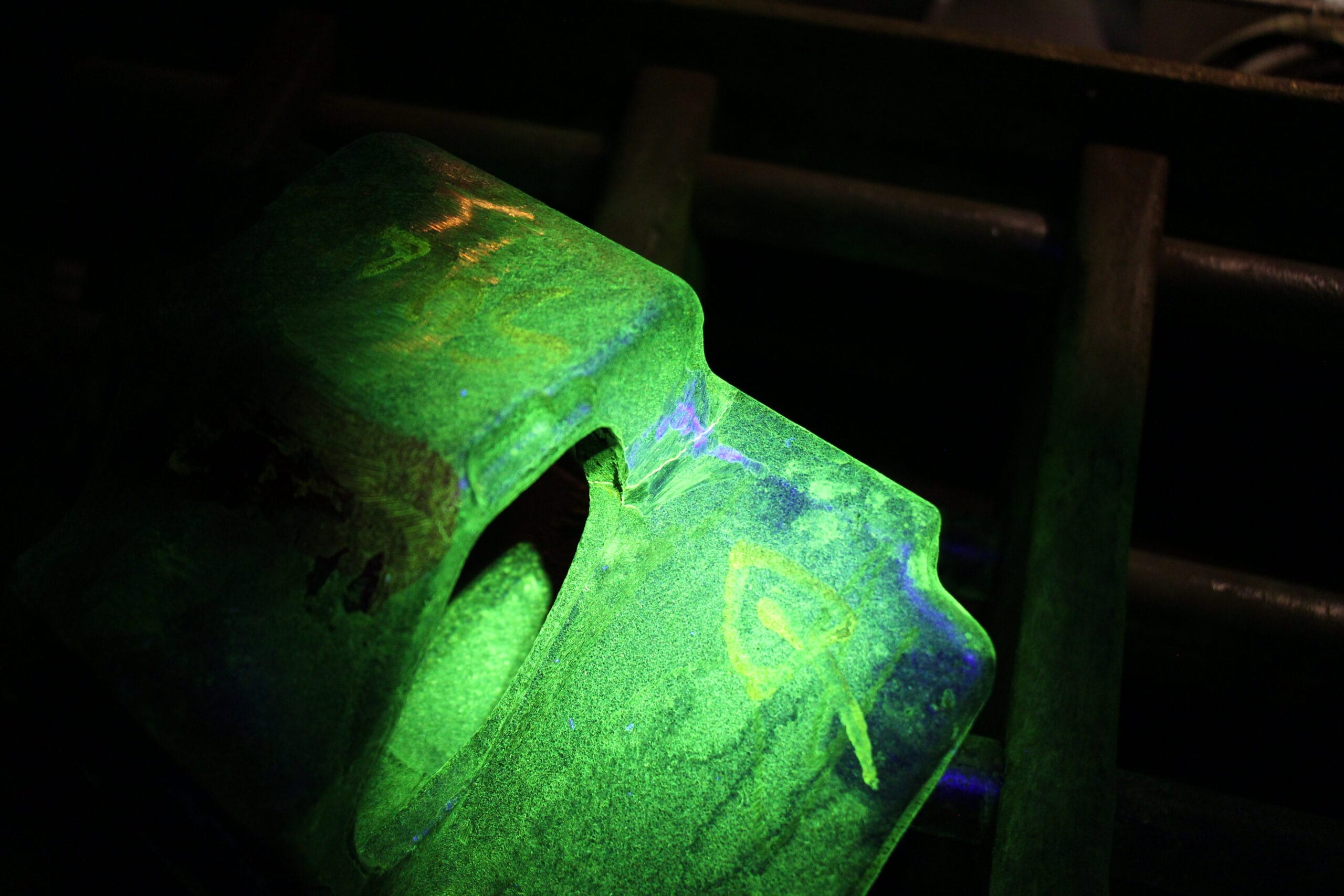
Liquid penetrant (LP) inspection is widely used to detect surface-open discontinuities in welded joints. However, this type of inspection presents a recurring challenge: false positives. Often, indications observed during the test do not correspond to real defects, but rather to artifacts caused by inadequate surface conditions or process execution. Based on ASTM E1417, ISO 3452-1, and ABNT NBR 15808 standards , this article explores how to avoid these interpretative errors.

Sources of False Positives

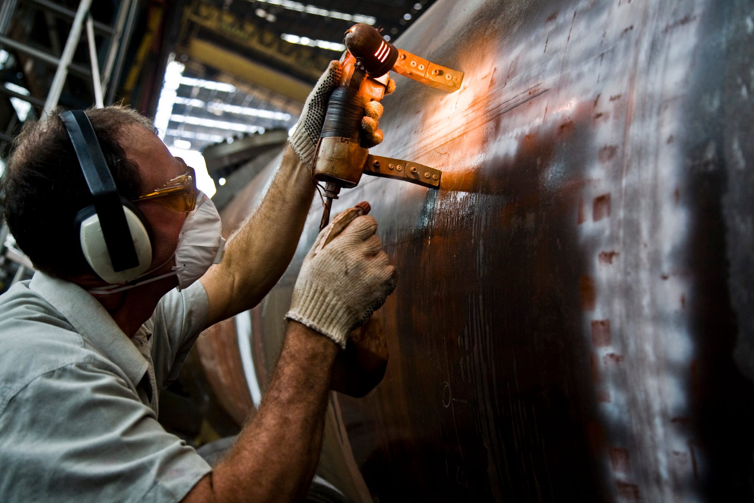
Welded surfaces often exhibit roughness, weld spatter, and metallic residue that retains the penetrant unevenly, creating marks that can be mistaken for discontinuities. To avoid this, surface preparation is essential. Removing slag, oxides, and contaminants by light blasting or chemical cleaning according to ISO 8501-1 is a critical step before product application.

Another important factor is the correct choice of penetrant type and sensitivity. On rough surfaces, highly sensitive products can cause background saturation, making interpretation difficult. In these cases, the use of penetrants with intermediate sensitivity (level 2 or 3) is recommended. Furthermore, the lighting must comply with ISO 3059, especially in industrial environments with varying levels of natural light. White light above 1000 lux or UV-A light between 1000 and 5000 μW/cm² is essential to ensure adequate visibility of the indications.

Removing excess penetrant is also a critical step. If done excessively, it can erase a true indication. If insufficient, it can create a “colored background” and mask defects. The developer application must be uniform, and the development time must be respected according to the type used: dry, wet, or non-aqueous.

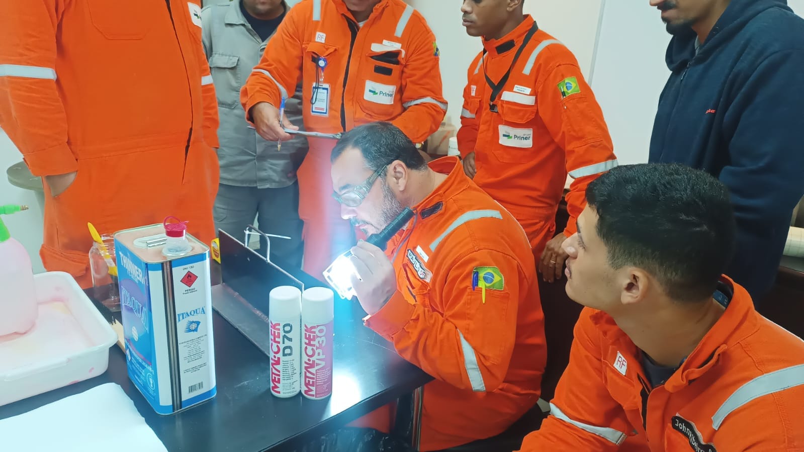
Finally, the inspector’s training makes all the difference. A professional trained according to ISO 9712 will have greater ability to distinguish between a true discontinuity and a surface artifact. Investing in training and continuous review of internal procedures contributes significantly to the quality and reliability of inspections.

Minimizing false positives in liquid penetrant testing (LP) of welds depends on three pillars: proper surface preparation, correct execution of the process, and professional qualification . These precautions increase the reliability of the test, reduce rework, and ensure more accurate decisions regarding the integrity of the welds being evaluated.

The accuracy of liquid penetrant (LP) weld inspection depends directly on the quality of surface preparation, the correct choice of penetrant, and the inspector’s experience. Standardizing the process according to international norms reduces the incidence of false positives and ensures greater reliability in acceptance or rejection decisions.

How to Interpret Indications in Magnetic Particle Testing: A Guide for Inspectors

Interpreting the readings obtained during a magnetic particle test is one of the most critical points in the process, especially when dealing with high-responsibility parts. Knowing how to differentiate between a relevant indication (a real defect) and an irrelevant indication (caused by geometry, field overlap, or contamination) is what guarantees the reliability of the evaluation and avoids unnecessary rejections or in-service failures.

The ASTM E1444 standard , as well as ISO 9934-1 , provides guidelines for identifying and classifying markings. According to these standards, a relevant marking is one that has sufficient extent, shape, and contrast to raise doubts about the integrity of the part. Irrelevant markings, on the other hand, typically appear in predictable locations such as holes, recesses, or areas of magnetic field concentration.

Furthermore, it is necessary to consider:

  1. Type of current used (direct or alternating);
  2. The direction of the applied field;
  3. The presence of residual fields. Inspectors should be alert to typical failure patterns, such as cracks parallel to the weld bead, laminations, non-metallic inclusions, or repetitive stress fatigue.

Reference photographs, comparison blocks, and previous reports can be used to aid in the decision.

Another important factor is documentation: all relevant information should be recorded with a description of the location, type of defect and, if possible, an image. Traceability is required by quality standards such as ISO 9001 and ASME .

Finally, the inspector’s qualification according to ISO 9712 is essential for them to have the technical expertise, critical thinking skills, and practical ability to correctly evaluate the test results.

The correct interpretation of the indications is not just a step in the PM process; it is the bridge between the technical test and the decision to continue or repair a component. Mastering this step reduces operational risks, strengthens asset safety, and generates cost savings for the industry.

Magnetic Particle Inspection: Concepts, Applications and Technical Standards

You probably already know that magnetic particle inspection (MPI) is a widely used technique in the Non-Destructive Testing (END) sector to detect surface and subsurface discontinuities in ferromagnetic materials. But in this article we will explore further, discussing the fundamental principles of the technique, its industrial applications, and the regulatory requirements that guarantee and guide the effectiveness and reliability of the method.

Fundamental Principles of Magnetic Particle Inspection

The PM technique is based on the magnetization of the material to be inspected. When there is a discontinuity on or near the surface, an interruption of the magnetic field occurs, forming magnetic poles in the region of the defect. By applying finely divided ferromagnetic particles to this area, they accumulate at the poles, making the presence of the discontinuity visible.

2. Principles of the Technique

Magnetic particle inspection is based on the creation of a magnetic field in the test specimen. When there is a discontinuity on or near the surface, an interruption occurs in the magnetic flux lines, resulting in a leakage field. The application of ferromagnetic particles, dry or suspended in liquid, allows these particles to accumulate in the region of the discontinuity, making it visible under white light or ultraviolet light (when fluorescent).

The main elements of the essay include:

  • Magnetization source : direct current, alternating current or pulsed current, depending on the desired inspection depth;
  • Types of magnetic particles : 1. visible: dry or wet or 2. fluorescent: used with UV-A light;
  • Magnetization techniques : direct contact, inductive, magnetic yoke (electromagnetic or permanent), among others;
  • Direction of the magnetic field : longitudinal, transverse, or multidirectional to maximize detection.

3. Industrial Applications

Magnetic particle technology is widely used in sectors where the structural integrity of metallic components is critical.

  • Aeronautics and Aerospace : inspection of landing gear, turbines and support structures;
  • Petrochemicals : pressure vessels, piping, flanges and welding;
  • Iron and Steel Industry and Metallurgy : bars, sheets, forgings and castings;
  • Automotive and Railway : axles, gears, wheels, rails and braking systems;
  • Power generation : hydraulic turbines, components for thermal and nuclear power plants.

4. Applicable Technical Standards

The execution of the magnetic particle test must follow the requirements established by nationally and internationally recognized technical standards:

4.1 Brazilian Standards (ABNT)

  • ABNT NBR NM 335 – Non-destructive testing: Liquid penetrant and magnetic particles (Terms and definitions);
  • ABNT NBR 9934-1 – Non-destructive testing: Magnetic particle testing (Part 1: General principles);
  • ABNT NBR 9934-2 – Part 2: Equipment;
  • ABNT NBR 9934-3 – Part 3: Technical details.

4.2 International Standards

  • ISO 9934 (Parts 1 to 3) – Non-destructive testing: Magnetic particle testing;
  • ASTM E709 – Standard Guide for Magnetic Particle Testing;
  • ASTM E1444/E1444M – Standard Practice for Magnetic Particle Testing;
  • ASME BPVC Section V, Article 7 – Requirements for testing boiler and pressure vessel components.

5. Advantages and Limitations

Advantages:

  • High sensitivity to detecting surface cracks;
  • Applicable to parts with complex geometry;
  • Immediate result;
  • Relatively low cost.

Limitations:

  • Applicable only to ferromagnetic materials;
  • Need for prior and subsequent cleaning;
  • Dependence of the magnetic field orientation on the discontinuity;
  • Subjective results when interpretation is visual.

Magnetic particle inspection remains an indispensable technique in quality assurance and structural integrity control programs across various industrial sectors. Its correct application, in accordance with regulatory requirements, is essential for reliable results. Mastery of technical parameters, inspector training, and proper equipment maintenance are critical factors in ensuring the effectiveness of the test.

Translate